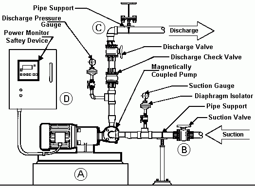
Positive Displacement Magnetically Coupled Pumps

A - Foundation and Baseplate
Foundation mass should be three times the mass of the driver and baseplate.
The foundation should be designed to avoid resonant vibration conditions originating from normal excitation forces at operating speed or multiples of the rotating speed.
Specify a baseplate that has machined mounting surfaces. This will cost a little more, but the additional cost will probably be saved at the shaft alignment.
Before setting the pump baseplate, chip the surface of the concrete pad to remove the cement rich surface concrete, called laitance. This will provide a stronger bond between the grout and concrete foundation.
The anchor bolts should be properly sized for the equipment being installed. Provide sufficient free length in the anchor bolt to allow for thermal expansion of the baseplate.
The Baseplate
- All machined mounting surfaces should be coplanar to within 0.002".
- All baseplate welds should be continuous and free of cracks.
- All cross bracing under the baseplate should have cutouts to allow for grouting.
- Vent holes (0.5" D) should be provided at each cross brace and corner.
- The baseplate should be designed with a minimum of 1.0" radius corners to prevent cracking of the grout.
- The mounting pads under the driver should provide for a minimum of 1/8" shims under the motor.
- Jacking screws should be provided to assist in shaft alignment of driver to pump.
- Machined mounting pads should extend 1.0" beyond pump and driver mounting feet on all sides.
For additional information on baseplates and baseplate installation, refer to the manufacturer's instruction manual or installation guides.