Vertically Mounted Sump Pumps
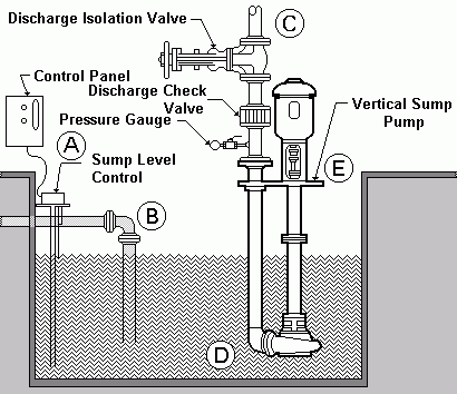
A - Sump Level Control Level Sensors
Level Sensors
The level sensor should be checked for compatibility with the liquid expected to be in the sump.
The level sensors should be located in a calm area of the sump. If the level sensors cannot be located in a calm area, it may be necessary to use a "Still Well."
The pump "STOP" level sensor should be positioned at a high enough level to maintain sufficient submergence of the pump suction connection.
The "START" and "STOP" level sensors should be separated by a sufficient distance to allow the pump motor to run long enough to dissipate the head generated by the inrush current at starting. This could be, depending on the size motor and its rating, from two to ten minutes or longer. Check with the motor manufacturer for details on the specific motor you will be using.
Control Panel
The control panel should include some type of time delay for either stop or start, to prevent rapid cycling of the pump. Care should be taken here to prevent the pump from running dry or flooding the sump (also see item four in level sensors, above).
If more than one pump is to be used, consider the use of an alternator to shift standby pumps between starts. Remember, standby pumps that set in a sump for an extended period of time may not work when needed.
If the control panel is located outside, consider the use of lightning arrestors and condensation heaters for the panel.
Including a run timer for the pump (or pumps if more than one) can be an inexpensive panel addition to help in scheduling maintenance.
B - Sump Inlet Piping
Locate the inlet piping as far as possible from the pump suction.
Where possible, locate the inlet piping below the sump liquid surface, to prevent drawing air into the liquid in the sump.
If the liquid entering the sump contains significant amounts of air or vapor, use baffles to allow the air to reach the surface before reaching the pump suction connection.
C - Discharge Piping
Support the piping independently of the pump. The piping should line up naturally with the pump connection and not need to be forced into position.
Provide a discharge valve for isolation of the pump, should maintenance be required.
Provide a discharge check valve located between the pump discharge connection and the discharge isolation valve. A check valve is normally required to prevent back flow of the pumpage through the pump.
Provide a pressure gauge or at least a gauge connection on the discharge as close to the pump discharge connection as possible and before any valves.
D - The Pump Suction
Locate the pump in a position that will minimize turbulence at the suction connection.
Insure a sufficient clearance between the pump suction connection and sump floor to allow liquid to enter the pump.
If large solids are possible in the sump, utilize a suction strainer.
E - Mounting
Support the pump. Provide a rigid structure under the pump mounting plate to reduce vibration and noise.
Typically, vertically mounted pumps need to be level. Before installation, review the manufacturer's instruction manual to determine the degree of level required for the particular pump being used.